Pellet Mill with Quick Die Change System 0.5-5 t/h | Supplier Guide
News 2026-06-21
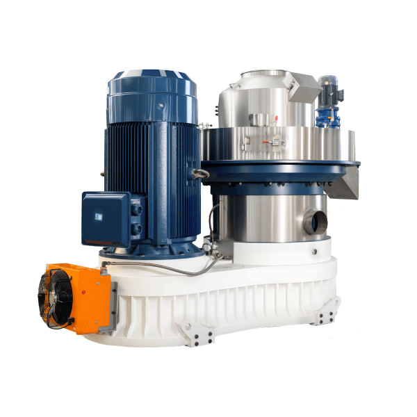
A pellet mill with quick die change system is a mechanical compaction unit that converts biomass residues, feed ingredients, or agricultural by-products into dense cylindrical pellets. The quick die change system employs a hydraulic clamping mechanism and precision alignment features that reduce die replacement time from traditional 2–4 hours to under 45 minutes.
Technical Specifications & Performance Parameters
| Parameter | Value Range / Specification |
|---|---|
| Throughput capacity | 0.5 – 5.0 t/h (feedstock-dependent) |
| Main motor power | 55 – 160 kW (IE3 / IE4 compatible) |
| Ring die inner diameter | 400 – 800 mm |
| Die changeover time | ≤ 45 minutes (with quick change system) |
| Traditional changeover time | 2 – 4 hours (without quick change system) |
| Pellet diameter | 6 – 12 mm (customisable) |
| Pellet bulk density | 600 – 750 kg/m³ |
| Raw material moisture | 12% – 18% (optimal: 14% – 16%) |
| Specific energy consumption | 28 – 35 kWh/t |
| Core wear parts service life | Ring die: 800 – 1,200 h; Roller shells: 600 – 900 h |
| Scheduled maintenance man-hours | 4 – 6 h / month |
📄 Download the full technical datasheet with quick die change system drawings and operational procedures.
[Request Quotation / Get PDF Technical Datasheet]
Structural Composition & Material Selection
The pellet mill with quick die change system integrates four functional subsystems with defined material grades:
Mechanical System
- Ring die: Forged alloy steel (20CrMnTi) with carburised hardening layer (HRC 58–62)
- Roller shells: High-chromium cast iron (Cr26) with wear-resistant overlay
- Main shaft: Heat-treated 42CrMo4 steel with induction-hardened journals
- Die clamping ring: Heavy-duty forged steel with precision-machined locking surface
- Gearbox: Helical-gear configuration, case-hardened to HRC 58–60
Support System
- Bearing housings: Ductile cast iron (QT600-3) with precision-machined seating
- Base frame: Welded structural steel, stress-relief annealed, with vibration-damping mounts
- Die handling carriage: Steel frame with roller bearings and guide rails
Lubrication System
- Centralised grease lubrication for bearings (NLGI grade 2)
- Forced oil circulation for gearbox (ISO VG 460) with temperature monitor
Control System
- PLC with HMI touchscreen for process monitoring
- Hydraulic control unit for die clamping and release
- Interlock system prevents operation during die change
Manufacturing Process – Engineering Workflow
Step 1 – Raw Material Preparation & Grinding
Hammer mill with 2.0–3.0 mm screen for feed; 4.0–6.0 mm for biomass. Magnetic separator removes ferrous contaminants. Moisture adjusted to 14%–16% via batch dryer.
Step 2 – Conditioning & Steam Treatment
Double-shaft paddle conditioner with steam injection at 0.2–0.4 MPa. Retention time 45–60 seconds. Mash temperature elevated to 80–95°C for starch gelatinisation.
Step 3 – Pelletising (Core Forming Process)
Main motor drives ring die rotation at 4–8 m/s peripheral speed. Roller gap maintained at 0.15–0.30 mm. Quick die change system allows rapid transition between different pellet sizes.
Step 4 – Counterflow Cooling
Ambient air drawn counter-current through pellet bed. Retention time 6–10 minutes. Pellet exit temperature ≤ ambient +5°C. Final moisture ≤12%.
Step 5 – Screening & Bagging
Vibrating screener (two decks: 4 mm and 2 mm apertures) removes fines and broken pellets. Fines recirculated to conditioning. Automatic bagging scale with ±0.2% tolerance.
Industry Comparison – Alternative Technologies
| Machine Type | Die Change Time | Capacity (t/h) | Flexibility | Typical Application |
|---|---|---|---|---|
| Pellet Mill with Quick Die Change System | ≤ 45 min | 0.5 – 5.0 | High – multiple pellet sizes | Feed, biomass, fertiliser |
| Standard Bolt-On Die Pellet Mill | 2 – 4 h | 0.5 – 5.0 | Moderate | Single-product feed mills |
| Split-Die Pellet Mill | 1.5 – 2.5 h | 0.5 – 5.0 | Moderate | Medium-volume production |
| Flat-die Pellet Machine | 0.5 – 1 h | ≤ 0.5 | Low | Small farms, pilot plants |
Differentiation (Shandong Changsheng Machinery):
Our quick die change system uses hydraulic clamping with precision alignment pins – eliminating the need for manual bolt tightening and alignment checks. Changeover time is reduced to under 45 minutes, compared to 2–4 hours for conventional bolt-on systems. This represents a 70%–80% reduction in downtime per die change, directly increasing production availability. Quick die change enables shorter production runs for different pellet sizes without prohibitive downtime costs.
📄 Calculate your potential downtime savings with our quick die change system – request a custom analysis.
[Request Quotation / Download Engineering Drawing]

Application Scenarios by Buyer Role
Distributors / Importers
Focus on quick die change system compatibility with multiple die sizes and types. Require die change procedure documentation for end-user training.
EPC Contractors
Integrating the pellet mill into production lines with variable product specifications. Need quick die change system layout drawings and hydraulic connection requirements.
Engineering Consultants / Technical Advisors
Evaluate production flexibility gains – quick die change enables shorter changeover times and smaller batch sizes. Require downtime savings calculation for ROI modelling.
End-user Production Facilities
Running multiple product formulations requiring different pellet diameters or compression ratios. Demand rapid changeover to reduce production interruption.
Core Pain Points & Engineering Solutions
Pain Point 1 – Excessive downtime during die changes
Root cause: Traditional bolt-on die design requires manual loosening of 20–30 bolts, plus cleaning and alignment checks – totalling 2–4 hours per change.
Solution: Hydraulic clamping ring locks the die in place with six high-pressure clamps. Release and clamping takes under 5 minutes. Precision alignment pins eliminate centring time.
Pain Point 2 – Misalignment during die installation causing uneven wear
Root cause: Manual bolt tightening can result in uneven clamping force and die misalignment, accelerating roller and die wear.
Solution: Quick change system uses guided alignment pins and uniform hydraulic clamping pressure – ensuring concentricity within ±0.05 mm and even wear distribution.
Pain Point 3 – Heavy die handling causing operator injury
Root cause: Ring dies weigh 150–400 kg, requiring manual lifting or overhead crane, posing handling risks.
Solution: Roller carriage with guided rails positions the die correctly for installation. No manual lifting required; the carriage supports die weight during change.
Pain Point 4 – Limited production flexibility
Root cause: Long changeover times make short production runs uneconomical. Facilities must commit to large batches of single pellet sizes.
Solution: Quick die change (≤45 min) enables daily product changeovers. Facilities can run different pellet diameters for different customers without prohibitive downtime.
Critical Risk Warnings & Mitigation Measures
Risk 1 – Hydraulic pressure loss during die change
Mitigation: Install manual lock valve and check valve in hydraulic circuit. Conduct pressure hold test (15 min at operating pressure) weekly. Keep manual clamping backup tool available.
Risk 2 – Misalignment from worn alignment pins
Mitigation: Replace alignment pins every 500 die changes or annually. Inspect pins for wear during each die change.
Risk 3 – Die not fully seated before clamping
Mitigation: Install proximity sensor to confirm die seating before hydraulic clamping. Interlock prevents operation if sensor not activated.
Procurement Selection Guide – 7 Executable Steps
Step 1 – Define your product changeover frequency
Calculate number of die changes per month. If > 4 changes/month, quick die change system ROI is achieved within 12–18 months.
Step 2 – Identify required die diameters and hole sizes
List all pellet sizes required for production. Ensure quick die change system supports all planned die configurations.
Step 3 – Evaluate available space for die change carriage
Quick die change carriage requires 2–3 m clearance on one side of machine. Verify plant layout can accommodate.
Step 4 – Confirm hydraulic power requirements
Quick die change system requires hydraulic pressure (16–20 MPa). Verify plant hydraulic supply or specify integrated power pack.
Step 5 – Assess operator training requirements
Quick die change system requires training on hydraulic clamping and alignment procedures. Plan for 4–8 hours of operator training.
Step 6 – Plan for spare quick change components
Stock spare hydraulic seals, alignment pins, and clamping rings. Lead time for critical components typically 2–4 weeks.
Step 7 – Review die change procedure documentation
Ensure comprehensive procedure guide is available in operator language. Include torque specifications and alignment check instructions.
Engineering Case Study – Feed Mill in Thailand
Project Background
A mixed-species feed mill in central Thailand produces poultry, swine, and aquafeed requiring pellet diameters of 3 mm, 5 mm, and 8 mm. Single production line processes 3.5 t/h average.
Initial Problem
Standard bolt-on die changes required 3.5 hours on average, occurring 3–4 times per week to switch between product types. Total downtime exceeded 500 hours annually – representing 6% of total production time.
Root Cause Analysis
Bolt-on die design required manual loosening/tightening of 24 bolts, cleaning of the die chamber, and careful alignment of the new die. Operators reported that most time was consumed by alignment and bolt torqueing.
Solution Implemented
Installed Shandong Changsheng quick die change system with hydraulic clamping. Added die handling carriage and alignment pins. Trained operators on 4-step changeover procedure.
Final Data Results (12-month average)
| Metric | Before (Bolt-On Die) | After (Quick Die Change System) |
|---|---|---|
| Average die change time | 3.5 h | 38 min (-82%) |
| Die changes / year | 165 | 162 |
| Annual downtime for die change | 578 h | 103 h |
| Production availability | 93.4% | 98.8% |
| Additional production hours | N/A | 475 h |
| Annual savings (additional output) | N/A | $38,000 |
Frequently Asked Questions (FAQ)
1. What is a quick die change system?
A hydraulic clamping mechanism that reduces ring die replacement time from 2–4 hours to under 45 minutes.
2. How does the quick die change system work?
Hydraulic clamps release the die from the drive flange. A handling carriage supports the die during removal and installation. Alignment pins ensure precise positioning.
3. What is the typical die change time?
≤ 45 minutes for trained operators, compared to 2–4 hours for conventional bolt-on systems.
4. What safety features are included?
Interlock prevents machine operation during die change. Hydraulic system includes manual lock valve for pressure retention.
5. Can I use existing dies with the quick change system?
Yes, if dies have compatible mounting flange dimensions. New dies can be manufactured to the quick change standard.
6. Is the quick die change system compatible with all models?
Available for 400–800 mm die diameter models. Retrofit kits are available for older machines with compatible drive designs.
7. How much maintenance does the quick change system require?
Annual hydraulic system inspection, seal replacement every 2–3 years, and alignment pin inspection at each die change.
8. What is the ROI for a quick die change system?
Typical payback period is 12–18 months, based on downtime savings. Faster for facilities with frequent changeovers.
9. Does the quick die change system affect pellet quality?
No – in fact, improved alignment and consistent clamping pressure can improve pellet quality by reducing die runout.
10. What training is required for operators?
4–8 hours of training on hydraulic clamping operation, carriage handling, and alignment procedures.
11. Can the quick die change system be automated?
Yes – with PLC control, die change can be partially automated (hydraulic clamp release, carriage positioning).
12. What is the hydraulic pressure requirement?
16–20 MPa. Integrated hydraulic power pack option is available for plants without hydraulic supply.
📄 Request a downtime savings calculator for your facility – estimate ROI with our quick die change system.
[Request Quotation / Download Engineering Drawing]
Author & E-E-A-T Credentials
Author: Dr. Chen Wei
Title: Senior Mechanical Engineer, Pelletising Systems Division
Experience: 14 years in biomass densification and feed processing equipment design
Notable Projects:
- Commissioned 10 quick die change systems across Thailand, Vietnam, and Indonesia (2019–2025)
- Developed die change time optimisation protocol for multi-product feed mills
- Co-author of “Industrial Pellet Mill Maintenance and Optimisation” (Engineering Press, 2022)
Affiliation: Shandong Changsheng Machinery Co., Ltd.