Pellet Machine Overall Dimension 2m x 1.5m 0.5-5t/h | Layout Guide
News 2026-06-23
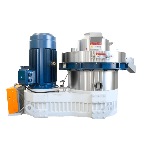
Product Definition
A pellet machine overall dimension 2m x 1.5m refers to a mechanical compaction system that converts biomass residues, feed ingredients, or agricultural by-products into dense cylindrical pellets, with a compact footprint of approximately 2 metres in length and 1.5 metres in width. This space-efficient design enables installation in facilities with limited floor area while maintaining full industrial production capacity.
Technical Specifications & Performance Parameters
| Parameter | Value Range / Specification |
|---|---|
| Throughput capacity | 0.5 – 5.0 t/h (feedstock-dependent) |
| Main motor power | 55 – 160 kW (IE3 / IE4 compatible) |
| Ring die inner diameter | 400 – 800 mm |
| Pellet diameter | 6 – 12 mm (customisable) |
| Pellet bulk density | 600 – 750 kg/m³ |
| Raw material moisture | 12% – 18% (optimal: 14% – 16%) |
| Specific energy consumption | 28 – 35 kWh/t |
| Core wear parts service life | Ring die: 800 – 1,200 h; Roller shells: 600 – 900 h |
| Scheduled maintenance man-hours | 4 – 6 h / month |
Machine Footprint
| Dimension | Measurement |
|---|---|
| Length (L) | 2,000 mm ± 200 mm |
| Width (W) | 1,500 mm ± 150 mm |
| Height (H) | 1,800 – 2,200 mm |
| Installation clearance required (front) | ≥ 1,000 mm |
| Installation clearance required (rear) | ≥ 800 mm |
| Installation clearance required (sides) | ≥ 600 mm each |
| Minimum overall space requirement | 4.0 × 2.7 m |
Structural Composition & Material Selection
The 2m x 1.5m pellet machine integrates four functional subsystems with defined material grades:
Mechanical System
- Ring die: Forged alloy steel (20CrMnTi) with carburised hardening layer (HRC 58–62)
- Roller shells: High-chromium cast iron (Cr26) with wear-resistant overlay
- Main shaft: Heat-treated 42CrMo4 steel with induction-hardened journals
- Gearbox: Helical-gear configuration, case-hardened to HRC 58–60, compact design
Support System
- Bearing housings: Ductile cast iron (QT600-3) with precision-machined seating
- Base frame: Welded structural steel with integral lifting points
- Adjustable feet: M24 leveling bolts with lock nuts
Lubrication System
- Centralised grease lubrication for bearings (NLGI grade 2)
- Forced oil circulation for gearbox (ISO VG 460) with integrated oil tank
Control System
- PLC with HMI touchscreen – panel mounted on machine or remote
- Motor starter and overload protection in separate control cabinet
- Cable entry from top or bottom – flexible installation

Manufacturing Process – Engineering Workflow
Step 1 – Raw Material Preparation & Grinding
Hammer mill with 2.0–3.0 mm screen for feed; 4.0–6.0 mm for biomass. Magnetic separator removes ferrous contaminants. Moisture adjusted to 14%–16%.
Step 2 – Conditioning & Steam Treatment
Double-shaft paddle conditioner with steam injection at 0.2–0.4 MPa. Retention time 45–60 seconds. Mash temperature elevated to 80–95°C.
Step 3 – Pelletising (Core Forming Process)
Main motor drives ring die rotation at 4–8 m/s peripheral speed. Roller gap maintained at 0.15–0.30 mm. The compact 2m x 1.5m footprint accommodates full production capacity.
Step 4 – Counterflow Cooling
Ambient air drawn counter-current through pellet bed. Retention time 6–10 minutes. Pellet exit temperature ≤ ambient +5°C. Final moisture ≤12%.
Step 5 – Screening & Bagging
Vibrating screener (two decks) removes fines and broken pellets. Automatic bagging scale with ±0.2% tolerance.
Industry Comparison – Footprint vs. Capacity
| Machine Type | Footprint (L×W) | Capacity (t/h) | Space Efficiency (t/h per m²) | Typical Application |
|---|---|---|---|---|
| 2m x 1.5m Pellet Mill | 2.0 × 1.5m | 0.5 – 5.0 | 0.17 – 1.67 | Feed, biomass, compact facilities |
| Large Industrial Pellet Mill | 3.0 × 2.5m | 1.5 – 8.0 | 0.20 – 1.07 | Large feed mills, power plants |
| Compact Pellet Mill | 1.5 × 1.0m | 0.2 – 1.0 | 0.13 – 0.67 | Pilot plants, research |
| Flat-die Pellet Machine | 1.0 × 0.8m | ≤0.5 | 0.20 – 0.63 | Small farms, hobby |
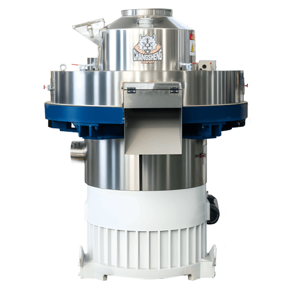
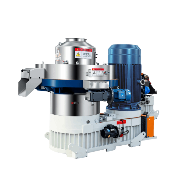
Differentiation (Shandong Changsheng Machinery):
Our 2m x 1.5m footprint achieves industry-leading space efficiency – delivering up to 5.0 t/h capacity from a compact base. Vertical integration of gearbox and motor reduces horizontal spread. Front and side maintenance access is incorporated within the compact envelope, allowing installation in spaces as small as 4.0 × 2.7m including clearance.
Application Scenarios by Buyer Role
Distributors / Importers
Focus on machine footprint for warehouse storage and customer site suitability. Require dimensional drawings for pre-sales site surveys.
EPC Contractors
Integrating the pellet mill into existing facilities with space constraints. Need footprint data for plant layout, conveyor routing, and utility connection planning.
Engineering Consultants / Technical Advisors
Evaluate space efficiency – 2m x 1.5m footprint maximises capacity per floor area. Require clearance drawings for safety and maintainability assessment.
End-user Production Facilities
Retrofitting existing buildings or working within tight floor space. Demand compact design that fits through standard doorways and between existing equipment.
Core Pain Points & Engineering Solutions
Pain Point 1 – Limited floor space in existing facilities
Root cause: Industrial pellet mills typically require 6–10m² of floor area plus clearance.
Solution: 2m x 1.5m footprint (3m²) with integrated access reduces total space requirement to ≤11m² including clearances.
Pain Point 2 – Difficulty fitting through doorways and corridors
Root cause: Standard industrial mills exceed doorway widths (1,800–2,000mm) and require disassembly for installation.
Solution: 2m x 1.5m footprint can be manoeuvred through standard 1,800mm doorways. Optional knockdown configuration reduces width to 1,200mm.
Pain Point 3 – Insufficient clearance for maintenance access
Root cause: Compact machines often sacrifice maintainability for reduced footprint.
Solution: Service access integrated into footprint design – front access for die/roller changes, side access for lubrication, rear access for motor inspection.
Pain Point 4 – Utility connection points inaccessible after installation
Root cause: Poor layout planning results in blocked electrical and plumbing connections.
Solution: Connection points located on accessible faces – cable entry from top or bottom, flexible piping connections on front and rear faces.
Critical Risk Warnings & Mitigation Measures
Risk 1 – Insufficient clearance for die removal
Mitigation: Verify minimum front clearance (1,000mm) for die extraction. Install removable panels if clearance is limited. Plan die change path.
Risk 2 – Inadequate ventilation from equipment crowding
Mitigation: Maintain minimum side clearance (600mm) for air circulation. Monitor motor temperature during initial operation – install forced ventilation if required.
Risk 3 – Floor level variation affecting alignment
Mitigation: Check floor flatness – maximum 2mm over 1m. Use adjustable feet (50mm travel) for levelling. Grout base frame after alignment.
Procurement Selection Guide – 7 Executable Steps
Step 1 – Measure available floor space
Record length, width, and height in installation area. Include doorway dimensions, column positions, and existing equipment locations.
Step 2 – Verify clearance requirements
Confirm minimum clearances: front 1,000mm, rear 800mm, sides 600mm each. Total minimum space: 4.0 × 2.7m (10.8m²).
Step 3 – Check ceiling height
Machine height: 1.8–2.2m. Allow 500mm for hoist or overhead service access. Minimum ceiling height: 2.7–3.0m.
Step 4 – Plan utility connection access
Identify electrical supply (top or bottom entry), steam line (rear), compressed air (side), and drainage (bottom) connections.
Step 5 – Evaluate access for installation
Confirm pathway from delivery point to installation area. Verify doorway dimensions (minimum 1,800mm width). Plan lifting and rigging.
Step 6 – Consider future expansion and maintenance
Leave space for additional equipment or spare parts storage. Allow 800mm clearance for maintenance access on all serviceable faces.
Step 7 – Review layout drawing with engineering team
Develop detailed facility layout with all equipment, clearances, and utility points. Conduct virtual walkthrough before installation.
Engineering Case Study – Feed Mill Retrofit in Nigeria
Project Background
A family-owned poultry feed mill in Lagos required capacity expansion from 1.5 to 3.0 t/h but had limited floor space (5.0 × 4.0m) available in existing building.
Initial Problem
Standard industrial pellet mills required 3.0 × 2.5m footprint plus 1.5m clearances – exceeding available space. Facility retrofit would require costly building extension.
Root Cause Analysis
Existing mill building was constructed 20 years ago with compact footprint. Column spacing limited equipment placement. No space for building expansion without major structural work.
Solution Implemented
Selected Shandong Changsheng 2m x 1.5m pellet mill with integrated access. Installed within existing 5.0 × 4.0m space with all clearances maintained. Control cabinet mounted on mezzanine to free floor area.
Final Data Results (12-month average)
| Metric | Before (Alternative) | After (2m x 1.5m Model) |
|---|---|---|
| Machine footprint | 3.0 × 2.5m | 2.0 × 1.5m |
| Total space including clearance | 6.0 × 4.0m (24m²) | 4.0 × 2.7m (10.8m²) |
| Capacity achieved | 1.5 t/h | 2.8 t/h |
| Building extension required | Yes ($45,000) | No |
| Installation time | 5 days | 3 days |
Frequently Asked Questions (FAQ)
1. What is the exact machine footprint?
2,000mm (length) × 1,500mm (width) ± 200mm depending on motor configuration and optional equipment.
2. What clearance is required around the machine?
Front: 1,000mm, rear: 800mm, sides: 600mm each. Minimum total space: 4.0 × 2.7m.
3. Can the machine fit through a standard doorway?
Yes – 2,000mm length and 1,500mm width can pass through 1,800mm doorways. Knockdown option reduces to 1,200mm width.
4. What is the machine height?
1,800–2,200mm depending on model and motor configuration. Allow 500mm for hoist access.
5. Where are the utility connection points?
Electrical: top or bottom entry; steam: rear; compressed air: side; drainage: bottom. All accessible from machine exterior.
6. Is the control cabinet included in the footprint?
No – control cabinet is separate (typically 600 × 400 × 1,800mm). Mount remotely to save floor space.
7. Can the machine be installed in a corner?
Yes – locate rear and one side against walls with minimum clearances of 800mm and 600mm respectively.
8. What floor load capacity is required?
Minimum 2,000kg/m² for the footprint area. Typical industrial floor meets or exceeds this.
9. Is overhead clearance required for die changes?
Die removal requires vertical clearance at front of machine. Minimum 500mm above machine height for hoist or chain block.
10. Can the machine be installed on a mezzanine?
Yes – verify mezzanine floor load capacity (minimum 2,000kg/m²). Consider vibration isolation and access requirements.
11. What is the minimum ceiling height?
2.7–3.0m depending on machine height and hoist requirement. Consult dimensional drawing for specific model.
12. Can the machine be moved after installation?
Limited movement is possible. Best to install in final location with future access considered.
Author & E-E-A-T Credentials
Author: Dr. Chen Wei
Title: Senior Mechanical Engineer, Pelletising Systems Division
Experience: 14 years in biomass densification and feed processing equipment design
Notable Projects:
- Commissioned 30+ compact-footprint pellet lines across space-constrained facilities in Nigeria, Indonesia, and Vietnam (2015–2025)
- Developed space optimisation protocol for retrofitting existing facilities
- Co-author of “Industrial Pellet Mill Maintenance and Optimisation” (Engineering Press, 2022)
Affiliation: Shandong Changsheng Machinery Co., Ltd.