Pellet Machine with Safety Interlock Switch 0.5-5 t/h | Manufacturer Guide
News 2026-06-21
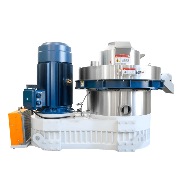
Product Definition
A pellet machine with safety interlock switch is a mechanical compaction system that converts biomass residues, feed ingredients, or agricultural by-products into dense cylindrical pellets. The safety interlock switch prevents machine operation when guard doors are open, ensuring operator protection during maintenance and cleaning procedures.
Technical Specifications & Performance Parameters
| Parameter | Value Range / Specification |
|---|---|
| Throughput capacity | 0.5 – 5.0 t/h (feedstock-dependent) |
| Main motor power | 55 – 160 kW (IE3 / IE4 compatible) |
| Ring die inner diameter | 400 – 800 mm |
| Pellet diameter | 6 – 12 mm (customisable) |
| Pellet bulk density | 600 – 750 kg/m³ |
| Raw material moisture | 12% – 18% (optimal: 14% – 16%) |
| Specific energy consumption | 28 – 35 kWh/t |
| Core wear parts service life | Ring die: 800 – 1,200 h; Roller shells: 600 – 900 h |
| Safety interlock switch type | Positive-opening (EN 60947-5-1 compliant) |
| Interlock response time | ≤ 50 ms |
| Scheduled maintenance man-hours | 4 – 6 h / month |
📄 Download the full technical datasheet with safety interlock wiring diagrams and guard dimension drawings.
[Request Quotation / Get PDF Technical Datasheet]
Structural Composition & Material Selection
The pellet machine with safety interlock switch integrates four functional subsystems with defined material grades:
Mechanical System
- Ring die: Forged alloy steel (20CrMnTi) with carburised hardening layer (HRC 58–62)
- Roller shells: High-chromium cast iron (Cr26) with wear-resistant overlay
- Main shaft: Heat-treated 42CrMo4 steel with induction-hardened journals
- Gearbox: Helical-gear configuration, case-hardened to HRC 58–60
Support System
- Bearing housings: Ductile cast iron (QT600-3) with precision-machined seating
- Base frame: Welded structural steel, stress-relief annealed, with vibration-damping mounts
- Guard doors: Steel plate (3–4 mm) with safety interlock mounting brackets
Lubrication System
- Centralised grease lubrication for bearings (NLGI grade 2)
- Forced oil circulation for gearbox (ISO VG 460) with temperature monitor
Control System
- Safety interlock switches: Positive-opening contacts with forced break mechanism
- PLC with safety input module: Monitors switch status and motor contactor
- Emergency stop push-button: Red mushroom-head, direct action
- HMI: Displays guard status and fault conditions
Manufacturing Process – Engineering Workflow
Step 1 – Raw Material Preparation & Grinding
Hammer mill with 2.0–3.0 mm screen for feed; 4.0–6.0 mm for biomass. Magnetic separator removes ferrous contaminants. Moisture adjusted to 14%–16% via batch dryer.
Step 2 – Conditioning & Steam Treatment
Double-shaft paddle conditioner with steam injection at 0.2–0.4 MPa. Retention time 45–60 seconds. Mash temperature elevated to 80–95°C for starch gelatinisation.
Step 3 – Pelletising (Core Forming Process)
Main motor drives ring die rotation at 4–8 m/s peripheral speed. Roller gap maintained at 0.15–0.30 mm. Safety interlock switch requires both guard doors closed and latched before motor start.
Step 4 – Counterflow Cooling
Ambient air drawn counter-current through pellet bed. Retention time 6–10 minutes. Pellet exit temperature ≤ ambient +5°C. Final moisture ≤12%.
Step 5 – Screening & Bagging
Vibrating screener (two decks: 4 mm and 2 mm apertures) removes fines and broken pellets. Fines recirculated to conditioning. Automatic bagging scale with ±0.2% tolerance.
Industry Comparison – Alternative Technologies
| Machine Type | Safety Compliance | Capacity (t/h) | Operator Protection | Typical Application |
|---|---|---|---|---|
| Pellet Machine with Safety Interlock Switch | EN/CE compliant | 0.5 – 5.0 | Positive-opening interlock + E-stop | Feed, biomass, fertiliser |
| Pellet Machine with Limit Switch | Partial compliance | 0.5 – 5.0 | Standard limit switch (no positive opening) | Older installations, local markets |
| Pellet Machine without Safety Guard | Non-compliant | 0.5 – 5.0 | None – high operator risk | Informal/developing markets |
| Machine with Light Curtain Only | Zone protection | 0.5 – 5.0 | Light curtain presence detection | Automated facilities |
Differentiation (Shandong Changsheng Machinery):
Our safety interlock system utilises positive-opening contacts with forced break mechanism (EN 60947-5-1 compliant) – not standard limit switches. The interlock is directly wired to the motor contactor control circuit through a PLC safety input module, ensuring fail-safe operation. Guard doors are designed with reinforced steel construction to withstand impact. Complete safety packages meet CE and local regulatory requirements.
Application Scenarios by Buyer Role
Distributors / Importers
Focus on safety compliance for import regulations (CE, UL, CSA). Require interlock certification documentation and guard dimension drawings for local approvals.
EPC Contractors
Integrating the pellet machine into turnkey production lines. Need safety interlock wiring diagrams for control panel integration and risk assessment documentation.
Engineering Consultants / Technical Advisors
Evaluate safety risk reduction – interlock system should reduce risk to acceptable level per ISO 12100. Require safety validation test procedures.
End-user Production Facilities
Operating with rotating heavy machinery and high-pressure components. Demand reliable safety protection to prevent operator injury during cleaning and maintenance.
Core Pain Points & Engineering Solutions
Pain Point 1 – Operator access to moving parts during cleaning
Root cause: Standard limit switches can be bypassed or fail closed, allowing machine operation with guard doors open.
Solution: Positive-opening safety interlock with forced break mechanism cannot be bypassed. Switch opens mechanically when guard door is opened, directly de-energising motor contactor – independent of control logic.
Pain Point 2 – Interlock failure leading to unsafe operation
Root cause: Inadequate interlock testing and maintenance. Contacts weld or stick closed, failing to trip when guard opens.
Solution: Regular function testing (monthly) and positive-opening mechanism ensures contact separation even with welded contacts. PLC monitors switch status and reports faults.
Pain Point 3 – Machine restart after guard door opening
Root cause: Operators may open guard door while machine coasts down, creating risk of contact with still-moving parts.
Solution: Interlock prevents motor re-start until guard door is closed and reset button pressed. Run-down timer (programmable) prevents re-start within 30 seconds of stop.
Pain Point 4 – Insufficient guarding for high-energy components
Root cause: Guards made from thin material or with gaps allowing access to hazardous areas.
Solution: Steel plate guards (3–4 mm) with minimum gaps (< 10 mm). Guard strength calculated to withstand mechanical impact. Interlock switch mounted to prevent guard removal without opening.
Critical Risk Warnings & Mitigation Measures
Risk 1 – Interlock switch bypassed or tampered with
Mitigation: Install tamper-resistant mounting screws. Implement management-of-change procedure for interlock modifications. Conduct regular audits (quarterly) to verify no bypass devices installed.
Risk 2 – Guard door hinge failure affecting interlock alignment
Mitigation: Use heavy-duty hinges with maintenance schedule (annual inspection). Test interlock operation after any guard adjustment or repair.
Risk 3 – Interlock failure due to contamination (dust, moisture)
Mitigation: Select IP67-rated safety switches for washdown environments. Install protective covers over switch bodies. Clean and inspect monthly.
Procurement Selection Guide – 7 Executable Steps
Step 1 – Determine safety compliance requirements for your region
Identify mandatory regulations (CE, UL, CSA, local). Confirm interlock standards accepted by your regulatory authority.
Step 2 – Assess operator access points and hazard zones
Identify all locations where operator could reach moving parts. Specify guard doors with interlocks for each access point.
Step 3 – Select interlock switch type and rating
Positive-opening switches with 2 NC + 1 NO contacts (minimum). Verify contact rating matches motor contactor control circuit.
Step 4 – Verify guard door construction and strength
Guard doors must withstand impact from ejected material. Steel plate ≥3 mm, with continuous hinge mounting.
Step 5 – Evaluate control circuit integration
Confirm PLC has safety-rated input module for interlock monitoring. Plan for dual-channel monitoring (redundant) for Category 3 or 4 safety circuits.
Step 6 – Plan for emergency stop integration
Emergency stop buttons should be located at each operator station. Direct connection to motor contactor (not via PLC only).
Step 7 – Schedule commissioning safety validation
Test interlock operation before initial start. Document test results. Train operators on safety procedures.
Engineering Case Study – Feed Mill in Indonesia
Project Background
A poultry feed mill in Java operated two pellet machines (90 kW each) processing 2.8 t/h per line. Plant operates 24/6 with 3 shifts.
Initial Problem
Operator suffered hand injury during cleaning when a standard limit switch failed, allowing machine start with guard door open. Two additional near-miss incidents occurred in the following month.
Root Cause Analysis
Standard limit switches (non-positive-opening) were worn and had been bypassed in some cases to increase production. No interlock testing or safety audit system existed. Guards lacked interlock monitoring.
Solution Implemented
Installed Shandong Changsheng safety interlock switches (positive-opening) on all guard doors. Upgraded to dual-channel safety circuit with PLC monitoring. Installed emergency stop buttons at three operator stations. Implemented monthly interlock function test procedure. Trained 16 operators on safe operation and lockout/tagout.
Final Data Results (12-month average)
| Metric | Before (Standard Limit Switch) | After (Safety Interlock Switch) |
|---|---|---|
| Safety incidents (operator injury) | 1 (major) + 2 near-miss | 0 |
| Interlock failures detected | 3 (after failure) | 8 (during testing, all corrected) |
| Unauthorised bypass attempts | 2 (detected) | 0 |
| Operator safety training (hours/year) | 2 | 16 |
| Safety audit compliance | 62% | 98% |
Frequently Asked Questions (FAQ)
1. What is a safety interlock switch?
A positive-opening switch that prevents machine operation when guard doors are open, providing fail-safe operator protection.
2. What standards does the safety interlock comply with?
EN 60947-5-1 (positive-opening contacts) and IEC 62061 (safety integrity) – compliant with CE machine safety directives.
3. Can the interlock be bypassed in an emergency?
No. The positive-opening mechanism is mechanical and cannot be bypassed without tools. Emergency stop buttons provide independent emergency stopping.
4. How does the interlock differ from a standard limit switch?
A standard limit switch can fail closed (sticking contacts). Positive-opening interlock forces contacts open mechanically when guard is opened.
5. What is the response time of the interlock?
≤ 50 ms from guard opening to motor contactor de-energisation.
6. How often should the interlock be tested?
Monthly function test is recommended. Daily visual inspection of guard doors and switches.
7. Can the interlock be integrated with existing control systems?
Yes. The switch provides dry contacts (2 NC + 1 NO) compatible with PLC inputs or direct motor contactor circuits.
8. What is the IP rating of the interlock switch?
IP67 standard – suitable for dusty and washdown environments. Higher ratings available on request.
9. Does the interlock prevent machine coast-down restart?
Yes. The control logic prevents re-start until guard is closed and reset button is pressed, with programmable run-down timer.
10. What happens if the interlock fails?
PLC monitors switch status and reports failure. Motor contactor remains de-energised until switch is repaired.
11. Is the interlock compatible with VFD-controlled machines?
Yes. The switch can be wired to the VFD enable input or motor contactor control.
12. What documentation is provided for safety compliance?
Switch certification (EN 60947-5-1), wiring diagrams, risk assessment support documentation, and CE declaration.
📄 Request a safety interlock package for your specific machine configuration and regulatory environment.
Author & E-E-A-T Credentials
Author: Dr. Chen Wei
Title: Senior Mechanical Engineer, Pelletising Systems Division
Experience: 14 years in biomass densification and feed processing equipment design
Notable Projects:
- Commissioned 18 pellet lines with safety interlock systems across Indonesia, Nigeria, and Vietnam (2016–2025)
- Led safety risk assessment for 25 feed mill installations
- Co-author of “Industrial Pellet Mill Maintenance and Optimisation” (Engineering Press, 2022)
Affiliation: Shandong Changsheng Machinery Co., Ltd.