Pellet Mill with Hydraulic Lifting Device 2-5 t/h Manufacturer Guide
News 2026-06-18
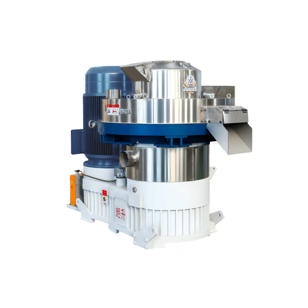
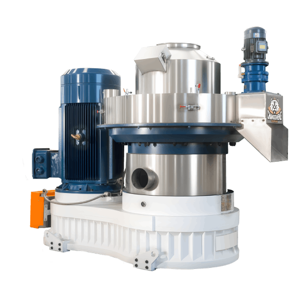
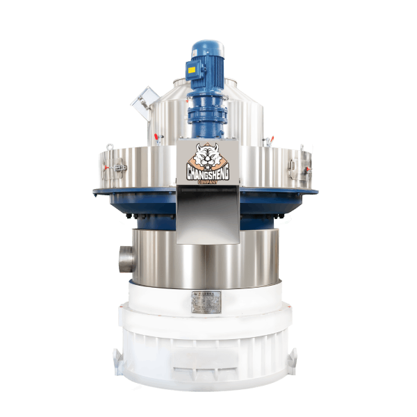
A pellet mill with hydraulic lifting device is a ring-die compaction system equipped with a hydraulic cylinder assembly that raises and lowers the die cover and clamp ring for rapid die change and internal inspection. It processes sawdust, wood shavings, and other biomass feedstocks into high-density cylindrical pellets while minimizing maintenance downtime.
Technical Parameters and Specifications
The following specifications are based on Shandong Changsheng Machinery SZLH series ring-die pellet mills equipped with hydraulic lifting device, configured for wood biomass processing.
| Parameter | Specification / Range |
|---|---|
| Production capacity (t/h) | 2.0 – 5.0 (feedstock dependent) |
| Main motor power (kW) | 90 – 160 |
| Ring die inner diameter (mm) | 550 – 760 |
| Ring die effective working width (mm) | 180 – 240 |
| Finished pellet diameter (mm) | 6 / 8 / 10 (customizable) |
| Finished pellet density (kg/m³) | ≥ 1,100 (ASTM E871) |
| Raw material moisture requirement (%) | 12 – 18 (optimal 14 – 16) |
| Specific energy consumption (kWh/t) | 60 – 85 |
| Ring die average service life (hours) | 2,500 – 4,000 |
| Roller shell service life (hours) | 1,200 – 2,000 |
| Hydraulic lifting cylinder stroke (mm) | 150 – 250 |
| Hydraulic system pressure (MPa) | 10 – 16 |
| Die change time (minutes) | 15 – 25 (single operator) |
| Estimated maintenance man-hours (hours/month) | 8 – 12 |
Download the complete hydraulic system drawing and maintenance schedule below this table.
Structural Composition and Material Selection
The pellet mill with hydraulic lifting device incorporates four integrated subsystems with specific material grades.
Mechanical processing system
The ring die is forged from 20CrMnTi alloy steel with vacuum carburizing to HRC 58-62 surface hardness. Roller shells use high-chromium cast iron with tungsten-carbide hardfacing at 6-8 mm thickness. The main shaft is machined from 40CrNiMoA alloy steel with quenched and tempered treatment. The clamp ring is fabricated from 42CrMo steel with precision-ground mating surfaces.
Hydraulic lifting system
The lifting cylinder is a double-acting hydraulic cylinder with a chrome-plated piston rod (hardness HRC 55-58). The cylinder barrel is manufactured from honed carbon steel tubing. The hydraulic power unit includes a gear pump (16 MPa rated), a relief valve, a directional control valve, and a 30-micron return filter. All hydraulic hoses are rated at 250 bar working pressure with SAE 100R2AT construction.
Support and bearing system
The main housing is cast from nodular iron (QT500-7) for vibration damping. Main bearings are SKF or FAG spherical roller bearings with C4 clearance to accommodate thermal expansion. The die mounting flange is precision-machined to ensure concentricity within 0.05 mm.
Lubrication system
Main shaft bearings receive forced oil circulation through a dedicated lubrication unit with 50-micron filtration and an oil cooler. Roller bearings are grease-lubricated via an automated single-point lubricator. Hydraulic system oil is filtered through a separate 10-micron filter on the return line.
Control system
The control panel houses a PLC (Siemens S7-1200) that interlocks the hydraulic lifting operation with motor status. A dedicated control pendant with emergency stop enables remote operation of the hydraulic lift. Sensors include hydraulic pressure transducer, cylinder position sensors, and safety interlock switches on the die cover.
Manufacturing Process (Engineering Steps)
Shandong Changsheng Machinery fabricates each pellet mill with hydraulic lifting device under ISO 9001 quality control. The manufacturing sequence follows these steps.
Step 1 – Ring die forging and pre-machining
Billets of 20CrMnTi are forged at 1150°C and then normalized at 870°C for 4 hours. Rough turning achieves dimensions within 1 mm of final size. Hardness is verified at HB 180-220 before drilling.
Step 2 – Ring die hole drilling and vacuum carburizing
A 24-spindle deep-hole drilling machine creates each die hole with coolant-through capability. Vacuum carburizing at 930°C for 6-8 hours is followed by high-pressure gas quenching. Tempering at 180°C achieves final hardness HRC 58-62. Case depth is verified at 1.2-1.5 mm.
Step 3 – Hydraulic cylinder machining and assembly
The cylinder barrel is internally honed to achieve surface finish of Ra ≤ 0.4 µm. The piston is turned and fitted with polyurethane seals and wear rings. The assembled cylinder undergoes a hydrostatic test at 1.5 times working pressure for 15 minutes with zero leakage.
Step 4 – Main housing casting and machining
QT500-7 casting is stress-relieved at 550°C. The bearing housings are line-bored to achieve a concentricity within 0.03 mm. All mounting surfaces are milled to achieve flatness within 0.1 mm per meter.
Step 5 – Final assembly and hydraulic system test
The hydraulic power unit is connected to the lifting cylinder and pressurized to 16 MPa. The cylinder is cycled through full extension and retraction 10 times to verify smooth operation and bleed air from the system. The safety interlock is tested by attempting to lift the die cover with the motor running.
Industry Equipment Comparison
| Equipment Type | Feedstock Suitability | Capacity (t/h) | Die Change Method | Typical Application | Why Choose Shandong Changsheng |
|---|---|---|---|---|---|
| Pellet mill with hydraulic lifting device (this unit) | Sawdust, shavings, chips | 2.0 – 5.0 | Hydraulic cylinder (15-25 min) | Industrial plants with frequent die changes | Single-operator die change; reduced maintenance labor |
| Manual clamp ring pellet mill | Any biomass | 2.0 – 5.0 | Manual bolts (45-75 min) | Small facilities, infrequent changes | Higher labor requirement; increased downtime per change |
| Quick-release mechanical clamp | Any biomass | 2.0 – 5.0 | Lever-operated clamps (25-40 min) | Medium-sized facilities | Lower initial cost but higher manual effort than hydraulic |
| Full-automatic die change system | Any biomass | 3.0 – 8.0 | Automated with robotic handling (5-10 min) | Large industrial complexes | Higher capital cost; complex maintenance |
Request a quotation with hydraulic lifting configuration options for your maintenance planning requirements.
Application Scenarios by Buyer Role
Procurement managers evaluate the maintenance labor savings from a pellet mill with hydraulic lifting device. They calculate the reduced downtime per die change and the impact on annual production targets. They also assess the hydraulic system reliability and spare parts availability.
EPC contractors specify these units for projects where operational flexibility is required. The hydraulic lifting device enables rapid changeover between pellet diameters without specialized tooling, which reduces installation complexity.
Engineering consultants assess the hydraulic safety interlock system and verify that the lifting cylinder meets fatigue life requirements per EN 982 for machinery safety. They review the cylinder mounting configuration to confirm alignment with the die cover structure.
End-user maintenance teams focus on the hydraulic system accessibility. The control pendant enables die cover lifting while the operator stands at a safe position. This reduces the risk of hand injuries compared to manual clamp ring disassembly.

Core Pain Points and Engineered Solutions
Pain point 1: Die change operations require two or more workers and cause excessive downtime.
Root cause: Manual clamp ring bolts require significant physical effort and careful alignment, especially on larger pellet mills.
Solution: The hydraulic lifting device supports the die cover weight and positions it precisely. One operator can complete a die change in 20 minutes using the control pendant.
Pain point 2: Uneven clamp ring torque leads to die distortion and premature failure.
Root cause: Manual tightening with torque wrenches may be inconsistent, and bolt tension varies across the clamp ring circumference.
Solution: The hydraulic cylinder applies uniform lifting force and the clamp ring is re-tightened using a torque-adjustable mechanism with calibration marking.
Pain point 3: The die cover is heavy and awkward to handle during inspection, increasing safety risks.
Root cause: Die covers on 550-760 mm dies weigh 150-250 kg, requiring lifting equipment for manual handling.
Solution: The hydraulic lifting device supports the cover at any position. A mechanical safety latch holds the cover open for internal inspection without hydraulic pressure.
Pain point 4: Hydraulic system leakage causes oil stains on the die chamber and contamination of the pellet feed.
Root cause: Seal wear in the lifting cylinder or hose fittings loosened by vibration.
Solution: Specified polyurethane seals with a service life of 8,000 cycles. All hose fittings are secured with wire-lock and inspected during the monthly maintenance schedule.
Risk Warnings and Mitigation Measures
Risk 1: Hydraulic cylinder drop hazard if the directional valve fails while the cover is open.
Mitigation: Install a pilot-operated check valve directly on the cylinder port that maintains position even if the supply line loses pressure. Test the check valve for holding capability annually.
Risk 2: Hydraulic oil fire hazard from oil spray onto the hot die surface.
Mitigation: Route all hydraulic hoses away from the die chamber and install fire-resistant hose sleeves (silicone-coated glass fiber). Locate the hydraulic power unit at least 2 meters from the pellet mill.
Risk 3: Pressure spike damage to the hydraulic pump from extending the cylinder against a mechanical stop.
Mitigation: Install a pressure relief valve set at 18 MPa. Include a pressure gauge on the control pendant and train operators to stop extension when the pressure reaches 14 MPa during normal operation.
Procurement Selection Guide (7 Actionable Steps)
Step 1 – Determine die change frequency
Calculate the number of die changes per month. If you change dies more than twice per month, hydraulic lifting provides significant downtime reduction. For less than one change per month, a manual clamp may be acceptable.
Step 2 – Define the pellet diameter range
Specify the pellet diameters you require. Confirm with the supplier that the hydraulic lifting mechanism accommodates all die sizes without requiring adapter rings or spacing adjustments.
Step 3 – Evaluate hydraulic power unit location
Decide whether to mount the power unit adjacent to the mill or remotely. Remote mounting up to 10 meters away reduces floor congestion but requires longer hoses and pressure drop calculation.
Step 4 – Verify electrical supply for hydraulic power unit
The hydraulic power unit typically requires 2.2 to 4.0 kW at 380-460 V. Confirm that the control system is interlocked with the main pellet mill motor to prevent lifting while running.
Step 5 – Assess workshop crane availability
Even with hydraulic lifting, a 200 kg die is still manually pulled from the chamber. Verify that an overhead crane or hoist is available for die extraction and insertion.
Step 6 – Review seal life specifications
Request the expected seal life in operating cycles. The cylinder should be designed for at least 10,000 cycles before requiring seal replacement.
Step 7 – Confirm hydraulic oil type and compatibility
Specify the required hydraulic oil viscosity grade (ISO VG 46 or VG 68 depending on ambient temperature). Verify that the power unit includes a 10-micron filter to maintain oil cleanliness.
Engineering Case Study
Project background: A commercial pellet plant in Spain operated two 132 kW pellet mills with manual clamp rings. The facility produced 4 mm, 6 mm, and 8 mm pellets for different markets and changed die diameters twice per week.
Initial problem: Each die change required two mechanics and 65 minutes of downtime. The clamp ring bolts were often overtightened, causing die face distortion and requiring early replacement at 1,800 hours. Annual maintenance labor for die changes exceeded 500 hours.
Root cause analysis: The manual clamp ring had 24 bolts requiring individual torque tightening. The heavy die cover needed a floor crane for lifting, which was not always available. Bolt torque calibration was not consistently verified.
Solution implemented: Shandong Changsheng Machinery supplied a retrofit hydraulic lifting device on the existing SZLH-560 pellet mill. The system included a 12 MPa hydraulic power unit, a control pendant, and a new clamp ring designed for the hydraulic cylinder. All existing dies were compatible with the new clamp ring.
Final data results:
Die change time: reduced from 65 minutes to 22 minutes (two-person to one-person)
Die face distortion: eliminated
Ring die life: extended from 1,800 hours to 2,900 hours
Annual maintenance labor savings: 340 hours
Hydraulic system reliability: zero failures in 18 months of operation
Return on investment: achieved in 7 months
Frequently Asked Questions
What is the lifting capacity of the hydraulic device?
The lifting cylinder is rated for the full weight of the die cover and clamp ring, typically 200-300 kg for the 550-760 mm die range.
Can the hydraulic lifting system be retrofitted to an existing pellet mill?
Yes, Shandong Changsheng offers retrofit kits for SZLH and compatible ring-die pellet mills. The existing die cover must be modified with a mounting bracket.
How long does the hydraulic lifting cylinder seal last?
The polyurethane seals are rated for 10,000 operating cycles. Under twice-weekly die changes, this equates to approximately 8 years of service.
What happens if hydraulic power is lost while the cover is open?
A pilot-operated check valve locks the cylinder position, preventing the cover from dropping. A manual lowering valve is provided for controlled descent.
Is special hydraulic oil required for this system?
ISO VG 46 hydraulic oil is standard for ambient temperatures between -10°C and 40°C. For higher temperatures, ISO VG 68 is recommended.
Does the hydraulic power unit require water cooling?
For standard duty with two changes per week, air cooling is sufficient. For high-frequency operation (more than one change per day), an oil cooler option is available.
Can the hydraulic lifting device be operated from the main control panel?
A dedicated control pendant is provided for local operation. The system can also be wired for remote control from the main panel if specified.
What safety interlocks are included?
The system includes a safety interlock that prevents motor start while the cover is open, and an emergency stop button on the control pendant.
How often should the hydraulic filter be changed?
The 10-micron return filter should be changed every 1,000 operating hours or when the pressure differential exceeds 0.5 MPa.
Is the hydraulic system compatible with food-grade or biodegradable oils?
Yes, the system seals are compatible with synthetic and biodegradable hydraulic fluids. Consult the supplier for seal material confirmation.
Request the full technical datasheet with hydraulic schematic and maintenance schedule.
Call to Action
Procurement managers and maintenance engineers may request the complete specification package including hydraulic system diagrams, cylinder certification, and retrofit installation guides.
Contact the engineering support team to review your die change frequency and receive a hydraulic lifting configuration recommendation.
Download the hydraulic installation drawing set and the full maintenance checklist.
Author and E-E-A-T Statement
Author name: Wang Tao
Position: Senior Mechanical Systems Engineer, Shandong Changsheng Machinery Co., Ltd.
Years of experience: 15 years in heavy machinery design and hydraulic system integration.
Representative projects: Designed the hydraulic lifting system for the SZLH-760 pellet mill line (2021) and completed field retrofit installations at three European pellet plants (2022-2023). Author of technical guidelines on safe die change procedures for ring-die pellet mills.
Affiliation: Shandong Changsheng Machinery