Pellet Mill with Overload Protection Relay 0.5-5 t/h | Manufacturer Guide
News 2026-06-20
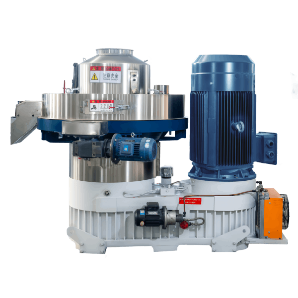
Product Definition
A pellet mill with overload protection relay is a motor-driven compaction system that converts biomass residues, feed ingredients, or agricultural by-products into dense cylindrical pellets. The integrated overload relay continuously monitors motor current and trips the circuit within milliseconds when current exceeds preset thresholds, preventing stator winding damage and drive train mechanical failure during sudden torque spikes.
Technical Specifications & Performance Parameters
| Parameter | Value Range / Specification |
|---|---|
| Throughput capacity | 0.5 – 5.0 t/h (feedstock-dependent) |
| Main motor power | 55 – 160 kW (IE3 / IE4 compatible) |
| Ring die inner diameter | 400 – 800 mm |
| Pellet diameter | 6 – 12 mm (customisable) |
| Pellet bulk density | 600 – 750 kg/m³ |
| Raw material moisture | 12% – 18% (optimal: 14% – 16%) |
| Specific energy consumption | 28 – 35 kWh/t |
| Core wear parts service life | Ring die: 800 – 1,200 h; Roller shells: 600 – 900 h |
| Overload relay trip class | Class 10 – Class 30 (adjustable) |
| Relay response time | ≤100 ms at 500% FLA (short-circuit); 2–10 s for thermal overload |
| Scheduled maintenance man-hours | 4 – 6 h / month (regular inspection + relay function test) |
📄 Download the full technical datasheet with relay coordination curves and wiring diagrams.
[Request Quotation / Get PDF Technical Datasheet]
Structural Composition & Material Selection
The pellet mill with overload protection relay integrates four functional subsystems with defined material grades:
Mechanical System
- Ring die: Forged alloy steel (20CrMnTi) with carburised hardening layer (HRC 58–62)
- Roller shells: High-chromium cast iron (Cr26) with wear-resistant overlay
- Main shaft: Heat-treated 42CrMo4 steel with induction-hardened journals
- Gearbox: Helical-gear configuration, case-hardened to HRC 58–60
Support System
- Bearing housings: Ductile cast iron (QT600-3) with precision-machined seating
- Base frame: Welded structural steel, stress-relief annealed, with vibration-damping mounts
Lubrication System
- Centralised grease lubrication for bearings (NLGI grade 2)
- Forced oil circulation for gearbox (ISO VG 460) with temperature monitor
Control System
- Overload protection relay: Electronic thermal overload with phase-loss detection
- Current transformers: 3-phase, ratio matched to motor FLA
- PLC with HMI: Displays motor current, thermal capacity, trip history log
- Manual reset switch with remote indication
Manufacturing Process – Engineering Workflow
Step 1 – Raw Material Preparation & Grinding
Hammer mill with 2.0–3.0 mm screen for feed; 4.0–6.0 mm for biomass. Magnetic separator removes ferrous contaminants. Moisture adjusted to 14%–16% via batch dryer.
Step 2 – Conditioning & Steam Treatment
Double-shaft paddle conditioner with steam injection at 0.2–0.4 MPa. Retention time 45–60 seconds. Mash temperature elevated to 80–95°C for starch gelatinisation.
Step 3 – Pelletising (Core Forming Process)
Main motor drives ring die rotation at 4–8 m/s peripheral speed. Roller gap maintained at 0.15–0.30 mm. Overload relay set to trip at 110%–115% of FLA with Class 20 curve for normal operation.
Step 4 – Counterflow Cooling
Ambient air drawn counter-current through pellet bed. Retention time 6–10 minutes. Pellet exit temperature ≤ ambient +5°C. Final moisture ≤12%.
Step 5 – Screening & Bagging
Vibrating screener (two decks: 4 mm and 2 mm apertures) removes fines and broken pellets. Fines recirculated to conditioning. Automatic bagging scale with ±0.2% tolerance.
Industry Comparison – Alternative Technologies
| Machine Type | Raw Material Adaptability | Capacity (t/h) | Motor Protection | Typical Application |
|---|---|---|---|---|
| Pellet Mill with Overload Protection Relay | Wide: 12%–18% moisture | 0.5 – 5.0 | Electronic thermal + phase-loss + short-circuit | Feed, biomass, fertiliser |
| Fuse-Protected Pellet Mill | Wide | 0.5 – 5.0 | Fuse-only (no thermal curve matching) | Older installations, low budget |
| Motor Circuit Breaker (MCB) Only | Wide | 0.5 – 5.0 | Magnetic trip only (no thermal protection) | Temporary / pilot installations |
| VFD with Integrated Overload | Wide | 0.5 – 5.0 | Electronic protection + speed control | Plants requiring process flexibility |
Differentiation (Shandong Changsheng Machinery):
Our overload protection relay provides Class 10–30 adjustable trip curves, enabling precise matching to motor thermal capacity and starting characteristics. Unlike fuse-only systems, the relay retains trip history and thermal memory for diagnostics. Phase-loss detection trips within 2 seconds, preventing single-phasing damage – a frequent failure mode in rural industrial grids.
📄 Request a relay coordination study for your specific motor and starting method.
[Request Quotation / Download Engineering Drawing]
Application Scenarios by Buyer Role
Distributors / Importers
Focus on relay compatibility with local voltage and frequency (380V/400V/415V, 50/60 Hz). Require multilingual HMI fault descriptions for end-user troubleshooting.
EPC Contractors
Integrating the pellet mill into complete production lines. Need relay auxiliary contacts (NO/NC) for DCS interlocking and emergency stop integration.
Engineering Consultants / Technical Advisors
Evaluate relay selection against motor starting current and grid capacity. Require coordination with upstream switchgear to avoid nuisance tripping.
End-user Production Facilities
Operating with variable feedstock and occasional foreign objects (stones, metal). Require reliable overload protection to prevent motor burn-out and minimise production interruptions.
Core Pain Points & Engineering Solutions
Pain Point 1 – Frequent motor burn-out from overcurrent events
Root cause: Inadequate protection devices (fuse-only or incorrectly sized MCBs) fail to respond to sustained overloads, allowing winding insulation to degrade.
Solution: Electronic overload relay with thermal memory models motor heating and cooling curves. Trip occurs before insulation temperature reaches Class F limit (155°C). Thermal memory retains accumulated heat even after power cycles.
Pain Point 2 – Nuisance tripping during normal starting
Root cause: Fixed-trip devices cannot differentiate between starting inrush (6–8× FLA for 3–5 seconds) and actual overload conditions.
Solution: Adjustable Class 10–30 trip curves – select Class 20 for high-inertia pellet mill applications. Relay ignores starting transients but responds to sustained overloads.
Pain Point 3 – Single-phase operation causing rapid motor failure
Root cause: One phase of a 3-phase supply opens due to blown fuse, loose connection, or grid imbalance. Motor continues running on two phases, drawing excessive current and overheating.
Solution: Relay includes phase-loss detection with 2-second trip delay – faster than thermal element alone. Prevents the 50%–70% of motor failures attributed to single-phasing.
Pain Point 4 – Inability to diagnose repeated tripping events
Root cause: Fuses provide no trip data – operators cannot determine why protection operated.
Solution: Relay stores last 5 trip events with current values, thermal capacity at trip, and phase conditions. HMI displays diagnostic data for root-cause analysis.
Critical Risk Warnings & Mitigation Measures
Risk 1 – Incorrect relay sizing leading to no protection
Mitigation: Relay FLA setting must match motor nameplate within ±5%. Verify using clamp-on ammeter during commissioning. Re-check if motor is rewound (FLA changes).
Risk 2 – Relay bypassed during emergency operation
Mitigation: Install tamper-proof cover over relay settings. Implement management-of-change procedure for any setting adjustment. Log all setting changes in maintenance records.
Risk 3 – Coordination failure with upstream protection
Mitigation: Ensure relay trip curve is faster than upstream circuit breaker (selectivity). Provide coordination study to electrical engineer. Test with primary injection annually.
Procurement Selection Guide – 7 Executable Steps
Step 1 – Calculate required throughput and select motor power
Match motor size to capacity target. For 3.0 t/h requirement, select 90–110 kW motor at 80% load factor.
Step 2 – Confirm site voltage, frequency, and fault current
Specify 380V/400V/415V, 50/60 Hz. Verify upstream transformer capacity and available short-circuit current for relay withstand rating.
Step 3 – Select appropriate trip class for starting duty
For pellet mills with high inertia (ring die + gearbox), select Class 20 or Class 30. Class 10 for low-inertia applications (<2-second start).
Step 4 – Verify relay interface with existing control system
Check auxiliary contact rating (AC-15 / DC-13) for PLC input compatibility. Confirm trip output is fail-safe (NC contact opens on trip).
Step 5 – Evaluate ambient temperature derating
If control panel ambient exceeds 40°C, derate relay continuous current rating by 5% per 10°C above. Consider panel cooling.
Step 6 – Plan for spare relay unit
Stock one spare relay with identical settings. Downtime cost typically exceeds spare relay cost within 2–3 hours.
Step 7 – Schedule commissioning test procedure
Perform primary injection test at 150% and 200% FLA to verify trip times. Document results in commissioning report.
Engineering Case Study – Feed Mill in Nigeria
Project Background
A poultry feed mill in Ogun State operated two pellet mills (75 kW each) processing maize-soya mash at 2.5 t/h per line. Site grid voltage fluctuates ±10% and experiences frequent lightning strikes.
Initial Problem
Over 18 months, the facility replaced 7 motors across both lines – each failure costing $4,200 in motor replacement and 6–8 hours of downtime. Root cause analysis showed 4 failures from single-phasing and 3 from sustained overload.
Root Cause Analysis
Existing fuses and magnetic MCBs provided no thermal protection. Single-phasing events from grid disturbances went undetected until motors overheated. Operators had no diagnostic data to identify failure modes.
Solution Implemented
Retrofitted both mills with Shandong Changsheng overload protection relays (Class 20, FLA set to motor nameplate). Added phase-loss detection and HMI with trip history. Trained operators on reset procedure and fault diagnostics.
Final Data Results (12-month average)
| Metric | Before (Fuse + MCB) | After (Overload Protection Relay) |
|---|---|---|
| Motor failures / year | 7 | 1 |
| Motor replacement cost (annual) | $29,400 | $4,200 |
| Unplanned downtime (hours/year) | 48 | 4 |
| Nuisance trips (starts) | N/A (fuses blow) | 2 (both due to grid transients) |
| Phase-loss events detected | 0 (undetected) | 6 (all logged, no motor damage) |
Frequently Asked Questions (FAQ)
1. What does an overload protection relay do on a pellet mill?
It monitors motor current continuously and trips the circuit when current exceeds safe levels for too long, preventing motor winding damage.
2. How is the relay different from a circuit breaker?
Circuit breakers protect against short circuits (magnetic trip). Overload relays protect against sustained overcurrent (thermal trip). Both are often used together.
3. What trip class should I select for a pellet mill?
Class 20 or Class 30 – pellet mills have high starting inertia and require longer starting time allowances.
4. Can the relay detect single-phasing?
Yes. The relay monitors all three phases and trips within 2 seconds if one phase is lost.
5. What is thermal memory and why is it important?
Thermal memory models motor heating and cooling. It prevents re-starting a hot motor too quickly, which could cause insulation damage.
6. How often should the relay be tested?
Annually, using a primary injection test to verify trip times at 150% and 200% FLA.
7. Can the relay be reset remotely?
Yes. Remote reset via PLC or push-button is supported. Manual reset can also be configured.
8. What happens if the relay trips during production?
The motor stops immediately. The HMI displays the cause. After investigation, press reset and re-start.
9. Is the relay compatible with variable frequency drives?
For VFD applications, use the relay on the line side (input) or specify VFD-compatible CT inputs. Consult factory for VFD integration.
10. What is the typical relay response time for an overload?
For a sustained overload at 150% FLA, trip time is typically 2–10 seconds depending on Class setting.
11. How does the relay account for ambient temperature?
The relay includes ambient compensation or requires derating above 40°C. Check manufacturer data for derating curves.
12. Can the relay communicate with my SCADA system?
Yes. MODBUS RTU communication is available for remote monitoring of current, thermal capacity, and trip history.
📄 Request a custom relay coordination study for your specific motor and site conditions.
[Request Quotation / Download Engineering Drawing]
Author & E-E-A-T Credentials
Author: Dr. Chen Wei
Title: Senior Mechanical Engineer, Pelletising Systems Division
Experience: 14 years in biomass densification and feed processing equipment design
Notable Projects:
- Commissioned 12 pellet lines with advanced motor protection systems across Indonesia, Vietnam, and Nigeria (2018–2025)
- Developed motor protection selection guide for tropical grid conditions
- Co-author of “Industrial Pellet Mill Maintenance and Optimisation” (Engineering Press, 2022)
Affiliation: Shandong Changsheng Machinery Co., Ltd.